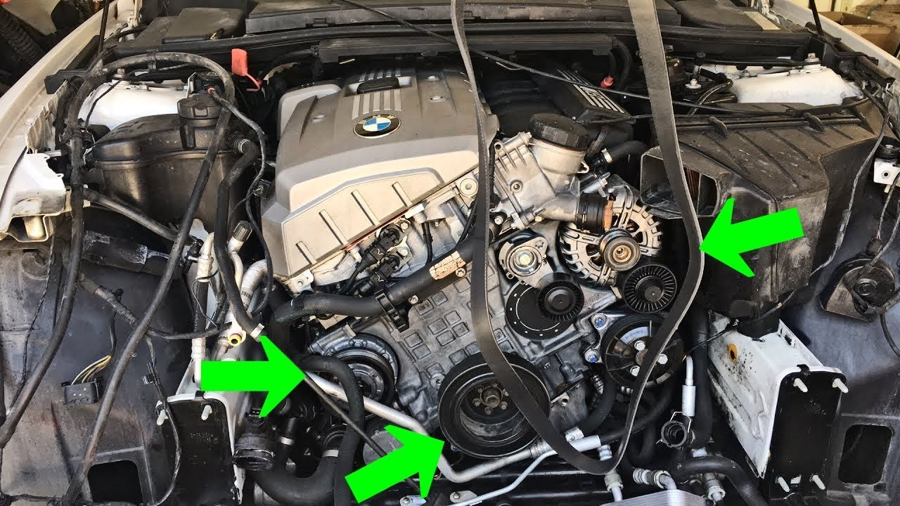
N55 Serpentine Belt Diagram – Belt diagrams are an essential tool for understanding the design and routing of belts through different mechanical systems. They offer visual representations of the way belts are positioned around various components, aiding mechanics, engineers, and DIY enthusiasts working on HVAC systems, or other belt-driven machines.
Types and applications of Belt Diagrams
- Serpentine belt diagrams can be employed when a single continuous, belt drives several devices.
- Timing belt diagrams demonstrate the position and alignment of a timing chain, that connects the crankshaft to camshaft(s) to enable to ensure the proper timing of valves.
- V Belt Diagrams illustrate the function and location of multiple V-shaped belts within older engines, or other special systems.
Key Components in Belt Diagrams
- A pulley is a device that has a circular shape around it and belts that are looped. It is a device that transfers the power from one component to the next.
- Belts are the flexible bands that transfer energy between pulleys.
- Tensioners keep the proper tension on the belt to prevent slippage and ensure the smooth operation.
What do I need to know in order to read a belt diagram
- Understanding symbols notations, symbols and how they are used helps you recognize the elements and routing patterns that are part of a diagram.
- Identifying key components such belts, pulleys, belts, tensioners, and pulleys allows you to visualise the layout of the system.
- Interpreting routing patterns reveals how the belt moves through it, and how it affects different elements.
A step-by-step procedure for creating a belt chart:
- Important Information: Measure and describe the belts and components accurately, and then arrange them in a correct order
- Sketch an initial layout: Draw an outline of the system’s layout, with each pulley and tensioner.
- Add Pulleys & Tensioners Label each pulley or tensioner with the appropriate component (e.g. alternator and power steering pumps).
- Create the Belt Routing Schema: Sketch out the route of your belt(s) around pulleys. Be sure to follow any industry or manufacturer standards.
- Reveal and improve your diagram.
Tips and Tricks to Belt Diagram Design
- Software tools are able to simplify the process of creating professional-looking diagrams.
- For creating a clear and functional belt diagram, it is essential to obtain accurate information from the manufacturer’s specifications, service manuals, or other reliable internet sources.
- Double-checking your diagram’s accuracy before you send the finalized version guarantees security and helps avoid issues during repairs.
Conclusion
For anyone who uses belt-driven systems, it is important to have a solid knowledge of how to construct belt diagrams. This will make you better prepared to tackle any task involving belts or pulleys by becoming familiar with the different types and components, as well as how to build them correctly. You can use our tips to produce precise and clear diagrams that increase efficiency and effectiveness.


