John Deere L120 Belt Diagram – Belt diagrams are an essential tool for understanding the layout and the routing of belts through different mechanical systems. They show the layout of the belts and their connections to different parts. This is helpful to mechanics, engineers and DIY-lovers when they work on HVAC systems, engines or any other belt-driven equipment.
Belt Types Diagrams
- Serpentine Belt Diagrams are utilized when a single continuous belt is driving multiple components like an alternator, power steering pump, compressor for air conditioners power steering pump, air conditioner compressor, and so on.
- Timing-belt diagrams illustrate where and how to align the timing belt. It connects the crankshaft with the camshaft(s) and assures the proper timing of valves.
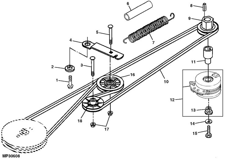
- V -belt diagrams show how V-shaped belts can be used in older engines or in other systems that are specialized.
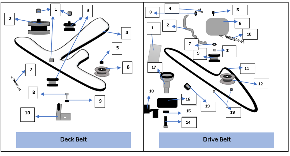
Belt Diagrams : Key Components
- Pulleys are circular structures around which belts are looped to transfer power from one component to the next.
- Belts transmit energy between pulleys.
- Tensioners maintain a proper tension on the belt to prevent sliding and ensure that it functions efficiently.
How can I look up a Belt Diagram
- Understanding symbols helps you identify components and routing patterns in a schematic.
- The recognition of key elements like belts and pulleys allows you to see the layout of the system.
- Interpreting routing patterns reveals how the belt travels through it, and how it affects different elements.
The following is a step-by- process guide for making a Belt Diagram
- Gather Important Info Take precise measurements and write down the belts, components, as well as their arrangement
- Sketch the Initial Plan: Sketch a system plan which includes each pulley or tensioner.
- Add tensioners and pulleys. Label each pulley with its component (e.g. power steering pump or alternator).
- Drawing the Belt Routing Diagram. Draw the belt route around pulleys.
- Make adjustments to your diagram.
Tips & Tricks for Belt Diagram Design
- Software tools are able to simplify the creation of professional-looking diagrams.
- Accurately gathering accurate information from manufacturer specifications, service manuals or trustworthy online sources is crucial to produce an accurate and valuable belt diagram.
- Double-checking for errors prior to finalizing your diagram guarantees precision.
Conclusion
If you’re a user of belt-driven machines, it’s essential to have a good understanding of how to create belt diagrams. If you’ve got a solid knowledge of the parts and the proper way to build them, you’ll be better equipped to tackle any task that requires pulleys or belts. Our suggestions and tricks can help you produce clear, precise diagrams to help you work more efficiently.
Gallery of John Deere L120 Belt Diagram


