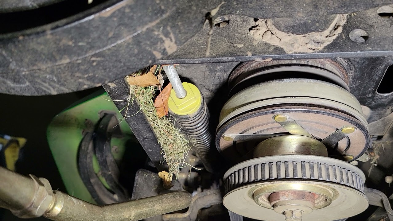
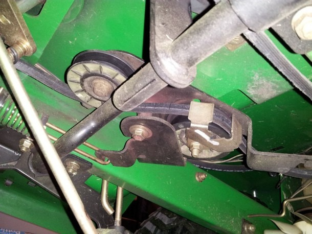
John Deere L111 Drive Belt Diagram – Belt diagrams assist you in understanding the way belts are placed in different mechanical systems. They provide visual representations of how belts are placed on various parts, helping mechanics, engineers, as well as DIY enthusiasts when working on HVAC systems, or other belt-driven machines.
Types of Belt Diagrams
- Serpentine belt diagrams are used in the event of a single, continuous belt driving multiple components like an alternator or power steering pump and air conditioning compressor.
- Timing-belt diagrams show how and where to align a timing belt. It connects the crankshaft with the camshaft(s), which assures the proper timing of valves.
- V-belt diagrams show the location of several V-shaped belts on older engines or special systems, each of which drives a separate component.
Key Components of Belt Diagrams
- A pulley is a device that is surrounded by a circle and belts that are looped. It is a device that transfers power from one element to the next.
- Belts, elastic bands that transmit power between pulleys, are called
- Tensioners maintain proper tension on the belt in order to prevent slippage and to ensure smooth operation.
How to read the Belt Diagram
- Understanding the meaning of symbols, notations and how they work can help you identify the components and routing patterns in a diagram.
- The recognition of key elements like belts and pulleys allows you to see the system’s layout.
- Understanding routing patterns can reveal how the belt travels through it and influences various components.
A step-by-step procedure for creating a belt chart:
- Get important information accurately measure, define and arrange components, belt(s) and their arrangement
- Sketch the Initial Plan: Sketch an outline of the system that includes each pulley or tensioner.
- Add Tensioners and Pulleys Label each pulley or tensioner with the appropriate component (e.g. alternator, power steering pumps).
- Draw the Belt Routing Diagram Draw the course of the belt(s) around pulleys, being sure to follow the specifications of the manufacturer or industry standards to ensure proper routing.
- Revise and enhance your diagram.
Tips and tips for making Belt Diagrams
- Utilizing software tools could make creating professional-looking diagrams much more simple, precise and effective.
- The key to creating a precise and useful belt diagram is obtaining accurate details from specifications of the manufacturer or service manuals.
- Double-checking any errors before completing your diagram guarantees precision.
Conclusion
Anybody who works with machines that are driven by belts must be able to draw belt diagrams. If you are familiar with various types of diagrams, their components, and how to construct them in a way that is correct You’ll be more equipped to tackle any task that involves pulleys or belts. Our tips and tricks can assist you in creating clear, precise diagrams that will help you work more efficiently.


