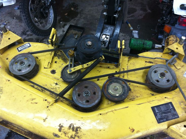
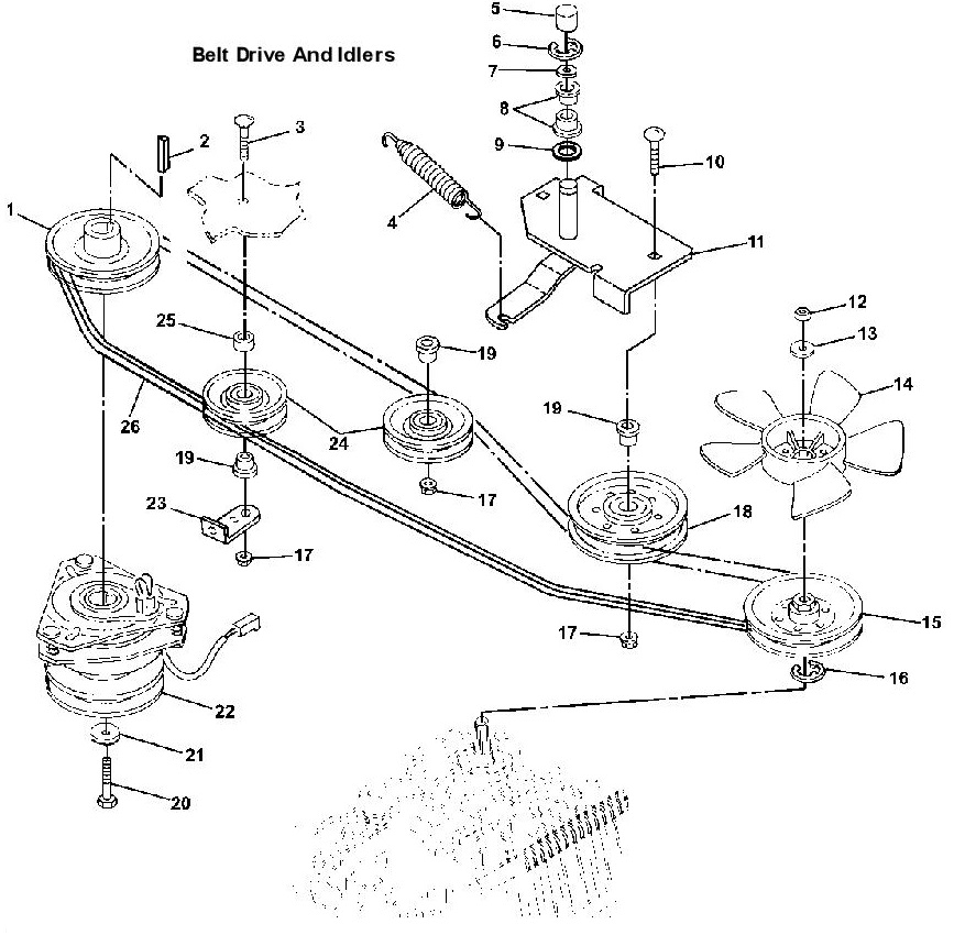
John Deere 245 Drive Belt Diagram – Belt diagrams can be utilized to help understand the flow and arrangement of belts within different mechanical systems. They provide visual representations of how belts are placed on various parts, helping engineers, mechanics, and DIY enthusiasts working on engines, HVAC systems, and other belt-driven machines.
Types of Belt Diagrams

- Serpentine belt diagrams are used when there is one, continuous belt driving multiple devices such as an alternator, power steering pump, and air conditioning compressor.
- Timing belt diagrams illustrate the location and alignment of a timing chain, which connects crankshaft to camshaft(s) to enable to ensure the proper timing of valves.
- Vbelt diagrams illustrate numerous V-shaped belts that are installed in older engines.
Key Components for Belt Diagrams
- The Pulleys are circular devices in which belts are wrapped around, transferring power to a single component.
- Belts are described as elastic bands that transfer power to pulleys.
- Tensioners maintain the proper tension on your belt, preventing slippage.
How to Read the Belt Diagram
- Understanding symbols notations, symbols and how they are used helps you understand the various components and routing patterns that are part of the diagram.
- Identifying important components such as pulleys, belts, belts, tensioners, and pulleys allows you to see the layout of the system.
- Understanding routing patterns allows you to understand how your belt is moving and impacts different parts.
This is a step by process guide for making a Belt Diagram
- Gather important information: Accurately measure, specify and organize components, belt(s) and their arrangement
- Sketch an Initial Layout Sketch an outline of the layout of the system, with each pulley and tensioner.
- Add Pulleys and Tensioners.
- Draw the Belt Routing Diagram Sketch out the route of the belt(s) around pulleys, following manufacturer specifications or industry standards for the proper routing.
- Improve your diagram.
Tips and Tricks to Belt Diagram Design
- With the right software tools, designing attractive and professional-looking diagrams is much easier, faster, and cost-effective.
- It’s essential to accurately gather information from service manuals or manufacturer specifications as well as other trustworthy internet sources in order to produce an efficient and accurate belt diagram.
- Checking the diagram twice for errors before you finalize it ensures accuracy and security. This eliminates any confusion that might occur during maintenance or repairs.
Conclusion
If you’re a user of belt-driven systems, it’s essential to have a good understanding of how to design belt diagrams. You’ll be better prepared to tackle any project that involves pulleys or belts if you know the various types of diagrams as well as their components. Use our tips and tricks to make detailed, clear diagrams that help you work more efficiently and more efficient.
Gallery of John Deere 245 Drive Belt Diagram


