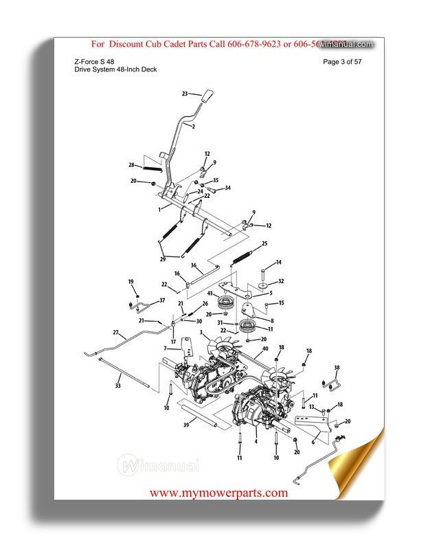
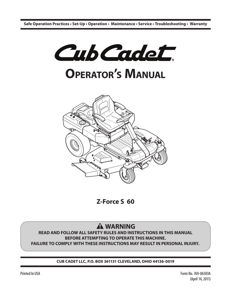
Cub Cadet Zforce 50 Belt Diagram – Belt diagrams can help you understand the way belts are placed within various mechanical systems. They provide the design of belts around various parts. This helps mechanics, engineers, and DIY-lovers when they are working on engines, HVAC, or any other equipment driven by belts.
Types of Belt Diagrams
- Serpentine belt diagrams can be utilized when there is a single continuous belt that drives multiple devices such as an alternator or power steering pump and air conditioning compressor.
- Timing Belt Diagrams illustrate the alignment and positioning of the timing belt which connects the crankshaft and camshaft(s) to ensure an accurate timing of the valve.
- V Belt Diagrams illustrate the location and purpose of various V-shaped belts inside older engines or special systems.
Belt Diagrams the most important components
- Pulleys, which are circular devices with belts that are looped around them. They transmit power from one part to the next.
- Belts are described as elastic bands that transmit energy to pulleys.
- Tensioners keep the belt in a tight position to prevent slippage.
How do I read a diagram of a belt
- Understanding symbols helps you identify parts and routing patterns within a schematic.
- Identifying important components such as pulleys, belts, tensioners and belts lets you visualise the layout of the system.
- The ability to understand routing patterns can reveal how the belt travels through it, and how it influences other components.
This is a step-by- procedure for creating a Belt Diagram:
- Gather important information: Accurately measure and specify the components, belt(s), and their location.
- Sketch the initial plan: Sketch a plan for the system which includes each pulley or tensioner.
- Add Tensioners and Pulleys: Label each pulley and tensioner with the appropriate component (e.g. power steering pump, alternator).
- Draw the Belt Routing Chart Draw the path of the belt in the direction of the pulleys. Check to see if it is in line with any industry or manufacturer guidelines.
- Revise and improve your diagram: Double-check all of your work for accuracybefore making any necessary adjustments to produce a clear, simple diagram.
Tips for Belt Diagram Design
- The use of software tools can help create professional-looking diagrams easier, precise and effective.
- For creating a clear and practical belt diagram, it is important to get accurate information from the specifications of the manufacturer, service manuals, and other reliable online sources.
- Double-checking for mistakes prior to finishing your diagram ensures accuracy and dependability, eliminating possible issues or confusion when performing repairs or maintenance.
Conclusion
Anyone working using belt-driven machines must learn how to draw belt diagrams. This will make you better equipped to handle any task involving belts or pulleys by gaining knowledge of the different types and components, and how to construct them properly. Use our suggestions to create clear and precise diagrams that improve efficiency and effectiveness.


