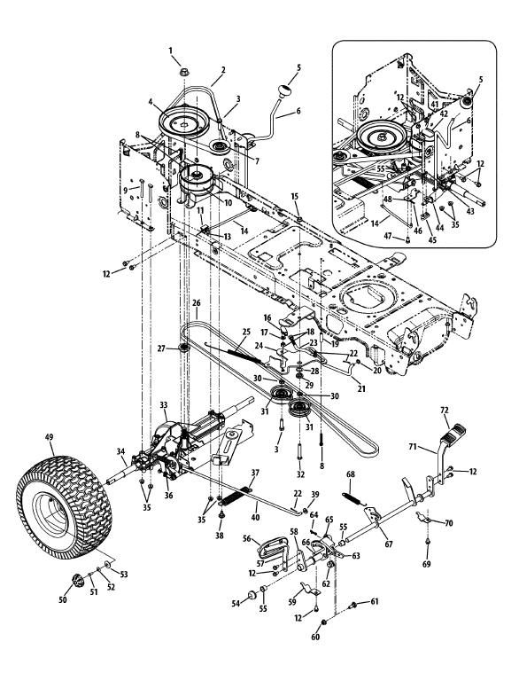
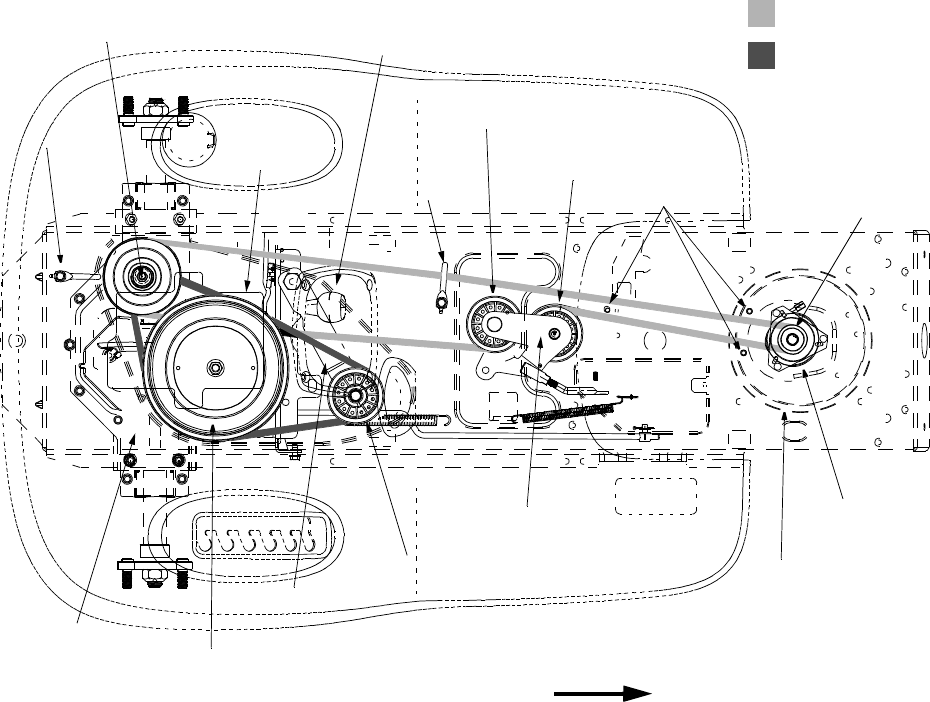
Cub Cadet Ltx 1040 Drive Belt Diagram – Belt diagrams assist you in understanding the way belts are placed in different mechanical systems. They provide the design of the belts and their connections to different components. This aids mechanics, engineers, and DIY-lovers when they are working on engines, HVAC, or any other equipment driven by belts.
Types and the Applications of Belt Diagrams
- Serpentine Belt Diagrams can be utilized when a single continuous belt is driving several devices such an alternator, power steering pump compressor for air conditioners power steering pump, air conditioner compressor, and many more.
- Timing-belt diagrams show the location and method of aligning a timing belt. It connects the crankshaft to the camshaft(s) that ensures proper valve timing.
- Vbelt diagrams show multiple Vshaped belts being placed in older engines.
Belt Diagrams: Key Components Diagrams

- The Pulleys are circular machines in which belts are wrapped around, transmitting energy to one part.
- Belts are elastic bands that transfer power from pulleys to ground.
- Tensioners keep the belt in a secure position to prevent it from sliding.
How to read a Belt Diagram
- Understanding symbols lets you recognize parts and routing patterns within a schematic.
- Identifying the most important components like belts, pulleysand belts, tensioners, and pulleys allows you to visualise the layout of the system.
- Understanding routing patterns can reveal how the belt moves through it and influences various elements.
This is a step-by-step tutorial for creating a belt diagram:
- Gather important information accurately measure, define and organize components, belt(s) and their arrangement
- Sketch an initial layout Create a sketch of the layout of the system with every pulley and tensioner.
- Add Pulleys & Tensioners: Label every pulley or tensioner with the corresponding component (e.g. alternator or power steering pumps).
- Draw the Belt Routing Diagram Draw the course of the belt(s) around pulleys, being sure to follow manufacturer specifications or industry standards for the proper routing.
- Reveal and improve your diagram.
Tips and Tricks to Belt Diagram Design
- The use of software tools can make creating professional-looking diagrams much easier to create, more precise, and efficient.
- It is crucial to gather accurate information from manufacturer specifications and service manuals to make a reliable belt diagram.
- Double-checking the accuracy of your diagram before you submit the final version ensures reliability and prevents any potential issues when you make repairs.
Conclusion
For those who use belt-driven systems, it’s essential to have a good knowledge of how to construct belt diagrams. If you have a good understanding of the components and how to correctly construct them, you’ll be better equipped to tackle any project involving pulleys or belts. These suggestions and tricks will assist you in creating clear and precise diagrams that can be more effective and efficient.
Gallery of Cub Cadet Ltx 1040 Drive Belt Diagram


