Belt Diagram For John Deere La105 – Belt diagrams are essential tools for understanding the design and the routing of belts in various mechanical systems. These diagrams show the way belts are positioned around various components. This is beneficial for engineers, mechanics as well as DIY enthusiasts and anyone who works on engines, HVAC systems, and other belt-driven equipment.
Types of Belt Diagrams

- Serpentine Belt Diagrams can be utilized when a single continuous belt is operating multiple components like an alternator, power steering pump, compressor for air conditioners power steering pump, and many more.
- Timing diagrams illustrate the way a timing belt is connected to the crankshaft. This is to ensure proper timing of an engine’s valves.
- V Belt Diagrams illustrate the function and location of various V-shaped belts inside older engines or special systems.
Principal Components of Belt Diagrams
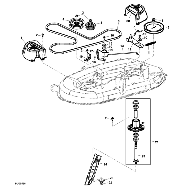
- Pulleys, which are circular devices with belts looped around them, transfer power from one part to another.
- Belts are described as elastic bands that transmit energy to pulleys.
- Tensioners maintain the proper tension of your belt to avoid slippage.
How do I find a belt diagram?
- Understanding symbols and notations helps identify elements and routing patterns in the diagram.
- The recognition of crucial components such as belts and pulleys allows you to see the layout of the system.
- Interpreting routing patterns reveals how the belt travels through it, and how it affects different components.

We’ve got an easy step-by-step guide to making belt diagrams:
- Important Information: Measure and specify components and belts accurately and arrange them properly
- Sketch the Layout of the Initial. Draw a sketch that shows the layout of the system. It also shows the position of each tensioner and pulley.
- Add Tensioners and Pulleys: Label every pulley or tensioner with the component that it is associated with (e.g. alternator or power steering pumps).
- Draw an a Belt Routing Diagram. Sketch the belt’s course around pulleys.
- Check and refine your diagram.
Tips, Tricks, and Strategies for Belt Diagram Construction
- Software tools can simplify the process of creating professional-looking diagrams.
- It is crucial to get accurate information from the specifications of manufacturers and service manuals to make a reliable belt diagram.
- Double-checking errors before finalizing your diagram ensures precision.
Conclusion
The ability and understanding to create belt diagrams are essential skills for anyone working using belt-driven systems. You’ll be more prepared to tackle any project that requires belts or pulleys if you are familiar with the various kinds of diagrams and their parts. Use our suggestions and tricks for producing clear, precise diagrams that make your work more efficient and productive.
Gallery of Belt Diagram For John Deere La105


