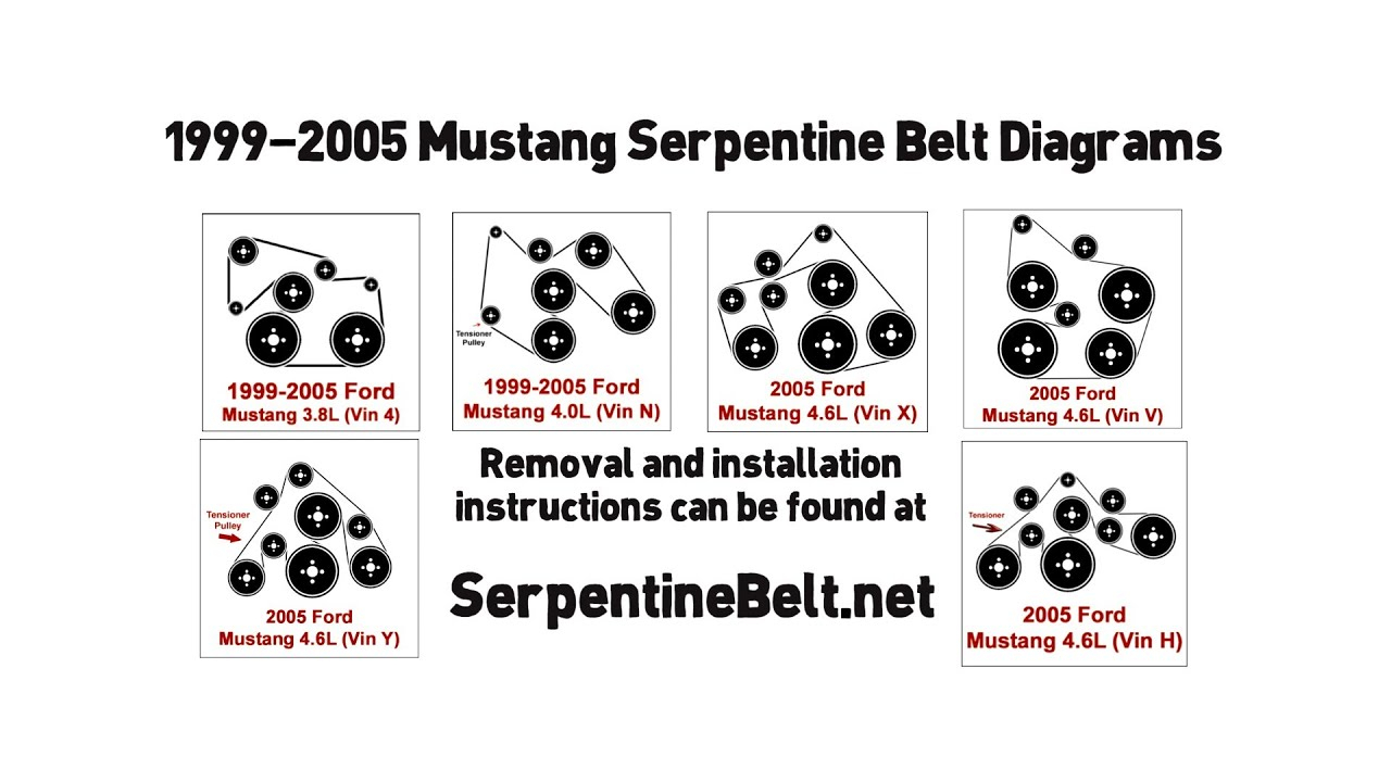
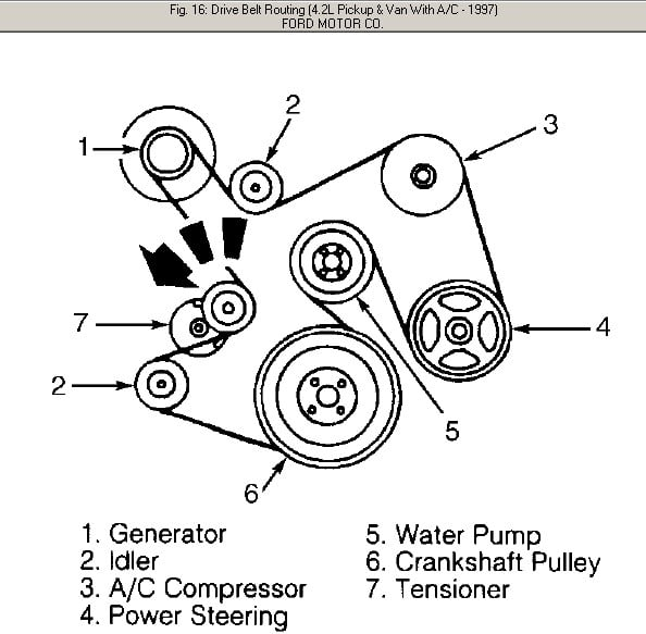
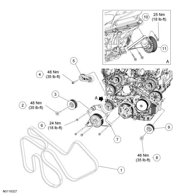
5.4 Triton Serpentine Belt Diagram – Belt diagrams help you understand the way belts are placed in various mechanical systems. They show the layout of belts around various components. This helps engineers, mechanics as well as DIY-lovers who are working on HVAC, engines, or other belt-driven equipment.
Types of Belt Diagrams
- Serpentine Belt Diagrams can be utilized when a single continuous belt is driving multiple devices such an alternator power steering pump air conditioner compressor power steering pump, air conditioner compressor, and so on.
- Timing belt diagrams depict the alignment and placement of a timing belt that connects the crankshaft with camshaft(s), ensuring that the valves are properly synchronized in the engine.
- V-belt diagrams show the arrangement of several V-shaped belts in older engines or special systems, each of which drives an individual component.
Belt Diagrams The Key Components
- Pulleys, circular devices that have belts that are looped around them. They transfer power from one area to another.
- Belts are the flexible bands that transfer energy between pulleys.
- Tensioners keep the belt in a straight position to prevent it from sliding.
How do I read a Belt Diagram
- The understanding of symbols and notations can assist you to discern the parts and routing patterns on an illustration.
- Identification of the most important components such as pulleys, belts and tensioners lets you to see the system’s layout.
- The ability to interpret routing patterns can reveal how the belt travels through it, and how it influences other components.
This is a step-by -step guide to creating an outline of a belt.
- Important Information: Measure and specify the belts and components accurately, and arrange them correctly
- Sketch the Initial Layout. Draw a sketch which shows the layout of the system. It also shows the position of each tensioner and pulley.
- Add Pulleys and Tensioners Label each pulley or tensioner with the component it is associated with (e.g. an alternator, power steering pump).
- Drawing the Belt Routing Diagram. Draw the belt route around pulleys.
- Reveal and improve your diagram.
Tips and Tricks to Belt Diagrams
- Utilizing software tools can make creating professional-looking diagrams much simpler, accurate, and efficient.
- The secret to creating an accurate and valuable belt diagram is accurately gathering information from manufacturer specifications or service manuals.
- Double checking for errors prior to finalizing your drawing will ensure that you are accurate and reliable. It also prevents problems or confusion during maintenance or repairs.
Conclusion
The ability and understanding to construct belt diagrams are essential skills for anyone working with belt-driven machines. If you are familiar with different types of diagrams, their components and methods of constructing them correctly, you’ll be better equipped to tackle any task that involves pulleys or belts. Our suggestions and tricks can aid you in creating clear and precise diagrams that will make your work more efficient.


